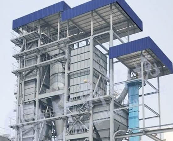
Searching for hazardous waste disposal solutions?
- Sub-systems
- Advantages of the Sub-systems
- Supplement Fuel
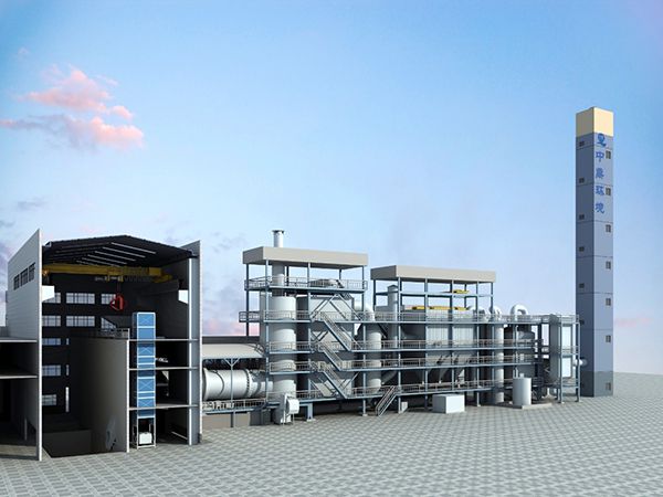
Zhongding Rotary Kiln Incineration System Process Flow
Rotary kiln incineration system is designed for the incineration and treatment of hazardous waste, medical waste, and general industrial solid waste. It is capable of handling hazardous waste in various forms such as solid, semi-solid, and liquid. Our advanced system ensures that the combustion process meets flue gas emission standards, resulting in high environmentally friendliness.
Pretreatment System
The waste first goes through pretreatment system. Waste with particle size smaller than 150mm is directly deposited into the waste storage pit. Large-sized materials or barrelled wastes are crushed by a crusher and then discharged into the storage pit. Wastes with different calorific values, compositions, and forms are matched based on their components, calorific values and other parameters.
After thorough mixing using a grab bucket, the wastes enter the feeding system.
Feeding System
- Bulk waste that has been properly mixed is conveyed by a grab bucket, discharged into the upper hopper of the apron plate feeder continuously and uniformly through a uniform feeding device.
- Barrelled waste and certain hazardous materials that can only be directly fed for incineration are conveyed into the head hopper by a vertical elevator. The elevator can serve as an alternative feeding channel in case of feeding system malfunctions.
- After pretreatment, the waste liquid is pressurized by a waste liquid pump, atomized with compressed air, and sent to the rotary kiln and secondary combustion chamber for incineration.
Rotary Kiln Combustion System
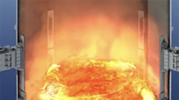
The waste enters the rotary kiln, stays for 30-120 minutes, undergoing a series of processes including drying, volatile analysis, and combustion. Through high-temperature incineration, the waste undergoes significant volume reduction. The incineration residue is continuously discharged through a water-cooled slagging system at the bottom of the secondary combustion chamber.
The approximately 850℃ flue gas generated from the rotary kiln enters the secondary combustion chamber, then undergoes thorough combustion with the assistance of secondary air. With the help of a combination burner, various organic compounds and dioxins are completely oxidized and decomposed.
Surplus Heat Utilization System
In the surplus heat utilization system, high-temperature flue gas generated from the secondary combustion chamber is directed to the heat recovery steam generator (HRSG), to recover energy by utilizing the flue gas heat. To minimize the emission of nitrogen oxides (NOx), the selective non-catalytic reduction (SNCR) method is employed.
The recovered heat from the HRSG generates steam, which is then utilized for various purposes. Portions of the steam are directed to cylinders for flue gas wet deacidification, associated equipment heat supply and other processes. Extra steam can be used for other purposes according to customer's requirements. Additionally, a condensation system can be installed to recover and reuse the condensate when steam is not used externally.
Flue Gas Quenching System
The final process is conducted in the flue gas quenching system. After heat recovery in HRSG, flue gas enters the quench tower to prevent the re-synthesis of dioxins in 200-550℃.
Once flue gas is discharged from the quench tower, it enters the dry deacidification tower, while hydrated lime powder and activated carbon powder are being injected. The hydrated lime in the flue gas undergoes acid-base neutralization reactions, while the activated carbon adsorbs heavy metals and dioxins.
The baghouse dust collector removes suspended particles from the flue gas, and the hydrated lime and activated carbon powder adsorbed on the filter surface undergo further acid-base neutralization reactions and heavy metal and dioxin absorptions. The fly ash is discharged and sent to the solidification workshop for solidification treatment via a screw conveyor and ash discharge valve.
The flue gas is then sent to the primary and secondary spray scrubbers by the induced draft fan. In the scrubbers, nitrogen oxides and sulfur dioxide are simultaneously absorbed and converted into water-soluble substances, along with a scrubbing device, nitrogen oxides are efficiently removed. Meanwhile, the alkaline solution reacts with acidic gases for flue gas denitrification.
Two-stage mist eliminators are installed in the upper part of the secondary deacidification tower to remove water mist from the flue gas, minimizing the water mist’s impact on electric field of the wet electrostatic precipitator. After passing through the mist eliminators, flue gas then enters the high-efficiency wet electrostatic precipitator with a temperature ~70℃ after. The strong electric field removes dust and water mist from the flue gas.
The flue gas is then heated to ~130-140℃ in the flue gas reheater, then finally discharged through the chimney.
Feed System and Combustion System
- The rotary kiln equips flexible seals with a long service life, excellent sealing performance, and a low air leakage rate (<1%).
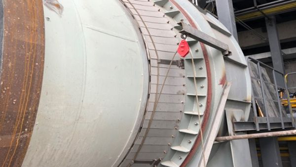 Flexible seals
- The rotary kiln equips a monitoring system to keep the operation status under control. This system takes comprehensive measurement of the kiln's temperature and monitors real-time condition of the refractory materials inside.
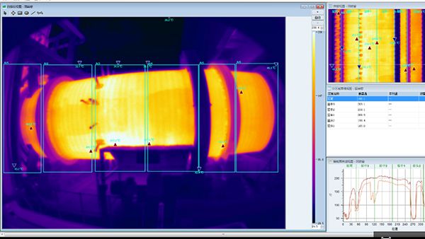 Infrared rotary kiln scanning and monitoring system
- The rotary kiln applies a combination burner, with valves and instruments (for control and adjusting) from top-tier suppliers. The burner features a compact structure and minimal space occupation. It is suitable for combustion of waste with multiple components. Other featured functions include independent control, automatic ignition, automatic flame monitoring, fire protection, fault alarm, etc. The burner also features high flame intensity, stable combustion, good safety, and a wide power adjustment range.
Primary air is supplied separately through the burner and water-cooled inlet chute's outer side into the rotary kiln. This offers good protection to the burner, meanwhile preheats primary air to improve thermal efficiency. The primary air is introduced through a special cyclone structure, ensuring thorough contact with the materials.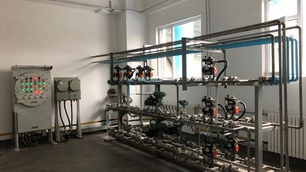 Kiln head combination burner
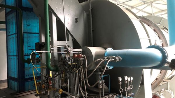 Kiln valve train
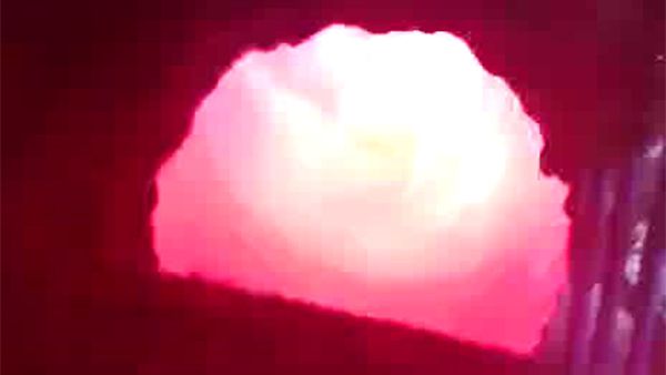 Kiln head cyclone primary air supply device
- The rear end of the rotary kiln adopts a replaceable guard plate structure, and the metal parts in contact with high-temperature gas are made of heat-resistant stainless steel (310S). This ensures long service life and minimal casting material detachment.
- The furnace space of the secondary combustion chamber is fully utilized, prolonging the residence time of flue gas in the chamber to over 3s. This design ensures a thorough mixing of flue gas and secondary air, enabling complete decomposition of harmful substances in the flue gas at 1100°C high temperature.
- The secondary air is introduced through the burner, which preheats the secondary air while cooling the burner.
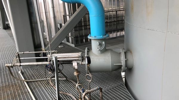 Burner of the secondary combustion chamber
Heat Recovery Steam Generator (HRSG)
Heat recovery steam generator (HRSG) is equipped with a multi-pass membrane wall boiler, ensuring thorough ash cleaning with sufficient shock wave soot blowers, leaving no dead corners.
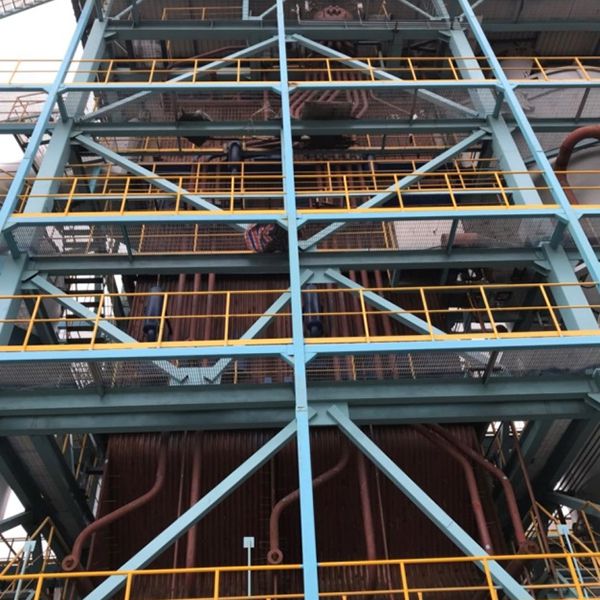 HRSG
HRSG 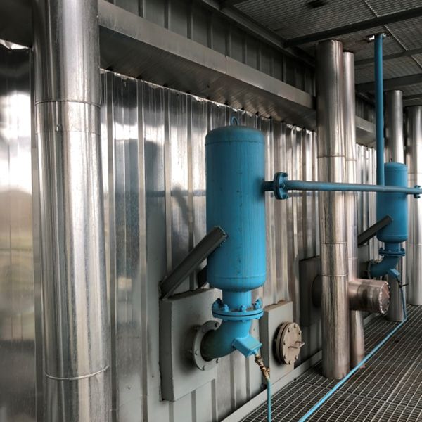 Shock Wave Soot Blowers of HRSG
NOX Control
- Temperature in the secondary combustion chamber is automatically controlled, ensuring stable combustion and appropriate temperature, thus to reduce NOX formation.
- Oxygen content during the incineration process is controlled to minimize the oxygen concentration in the secondary combustion chamber to reduce NOX generation.
- Dual-stage combustion: keep a lower oxygen content in the rotary kiln to allow the material to undergo primary combustion in a weak reducing atmosphere, promoting the decomposition of nitrogen compounds into N2. Then, carry out thorough combustion in the secondary combustion chamber to completely eliminate harmful substances.
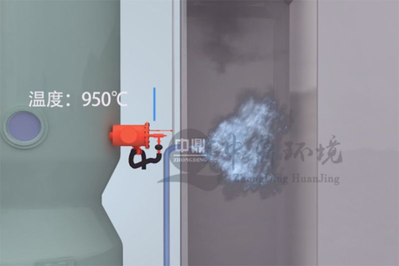
- Utilize SNCR system to remove nitrogen oxides in the flue gas. Protective measures are implemented to minimize the impact of atomized liquid on the tube walls.
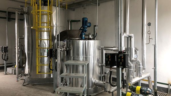 Urea Blending and Storage System
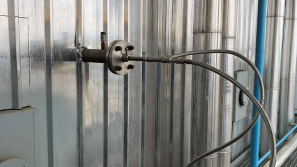 Surplus Heat Utilization System SNCR Nozzle
Dioxin Control
- The design of the rotary kiln and secondary combustion chamber fully utilizes the "3T+E" principle to ensure thorough decomposition of dioxins.
- The quench tower and the flue gas duct entering it are designed based on gas simulation experiment results conducted by Japanese experts, ensuring no gas deviation. The flue gas from the heat recovery boiler is rapidly cooled from 550°C to 180°C within 1 second.
- High-quality rapid cooling nozzles from top-tier suppliers, with an atomization capacity 2 times over the designed capacity. When sudden interruption of cooling water supply occurs, the system automatically switches to a pressure compensation water supply system for cooling, ensuring the safety of equipment in subsequent processes (dust collector filter bags, deacidification tower, etc.).
- Quenching water amount is regulated by an automatic valve, which is interlocked with the outlet temperature of the quenching tower. This ensures that the outlet temperature of the quenching tower does not exceed 180°C, thus to protect equipment in subsequent processes.
- The quenching tower allows for spraying of de-acidified and salt-containing wastewater to achieve zero wastewater discharge from the incineration system.
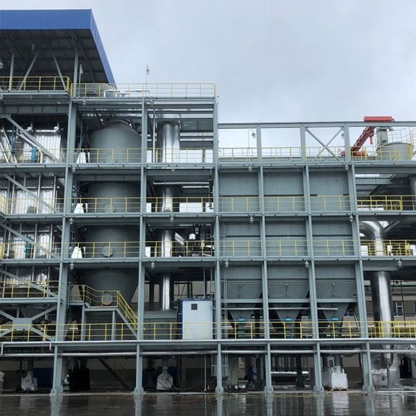 Quenching tower
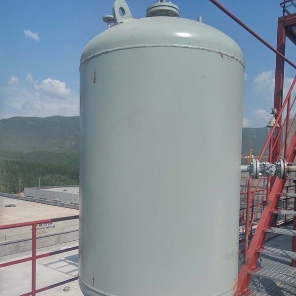 Constant pressure water supply tank
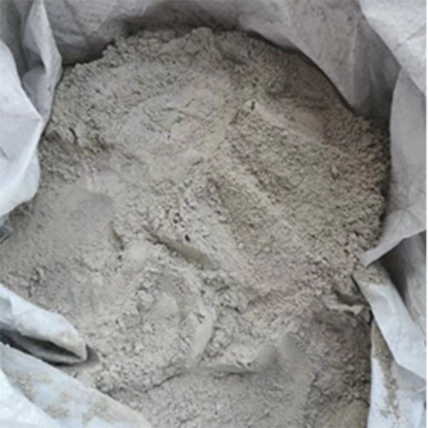 Fly ash discharged from quenching tower bottom after adding salt inhibitor
Control System of Waste Incineration System
- The incineration system is highly automated, employing a distributed control system (DCS) for computer-controlled unit start/stop, data processing, and parameter adjustment|. The DCS includes data acquisition and processing system, analog control system, sequential control system, etc.
- For critical areas or interlocking control points, three instruments (thermocouples, differential pressure gauges, etc.) are installed to ensure accuracy of detection data and stable operation of the system.
Others
- Steel structure, strong load-bearing capacity, smooth access in all directions - front and rear, left and right, and up and down - on each platform. Convenient for maintenance and operation.
- The slag extractor features wide width, ensuring an unobstructed interface with the secondary combustion chamber. This prevents the formation of bottom and hanging coking of the secondary combustion chamber. The equipment equips a large-diameter transmission chain and wear-resistant scraper, while the bottom is equipped with a wear-resistant alloy rail, it thus possesses a high overall load-bearing capacity and is designed with overload protection function, enabling extended periods of continuous operation.
Diesel, natural gas
- Based on years of design and on-site operational experience, Zhongding utilizes a large-diameter secondary combustion chamber to reduce the gas velocity, effectively promote sedimentation.
- The secondary combustion chamber is designed with an inclined bottom to minimize the residence time of the gas at the bottom, reducing the occurrence of coking.
- The refractory material of the slag outlet in the secondary combustion chamber is positioned at least 200mm below the slag outlet of the rotary kiln to prevent coke hanging.
- The secondary combustion chamber is equipped with multiple observation and coke-busting holes. The manhole doors are enlarged to 800*1200mm for easy coke cleaning.
- Near the bottom of the secondary combustion chamber, close to the tail end of the rotary kiln, a high-calorific-value waste liquid injection port (or coke-cleaning burner) is installed to facilitate temperature rise for coke cleaning as needed, and can be withdrawn when not in use.
- A designated inlet is designed for injecting anti-coking agent into the chamber, the agent can be injected proportionally when necessary.
Refractory Materials: direct heating can cause the refractory materials of the kiln to become extremely dry, potentially leading to cracks. It is essential to inspect the kiln for cracks and promptly carry out repairs to avoid further damages. Failure to address this issue can result in the detachment of refractory materials, leaving the kiln exposed to high temperatures.
- Burner: The nozzle, cone, and sensors of the burner should be checked for wear and/or damage.
- Sealing Performance: During operation, high temperatures can sometimes cause deformation of the seals. Deformed seals are ineffective and can lead to unnecessary air leakage into the kiln, disrupting the reactions inside.
- Alignment: Worn or damaged tires/wheels, gears/perimeter, and thrust rollers all indicate poor alignment. If you notice severe vibrations, the kiln may be misaligned.
- Prevention is key for rotary kiln maintenance. Regular inspections and repairs of refractory materials, burners, seals, and alignment are necessary to ensure efficient operation and extend the lifespan of the rotary kiln itself.
-
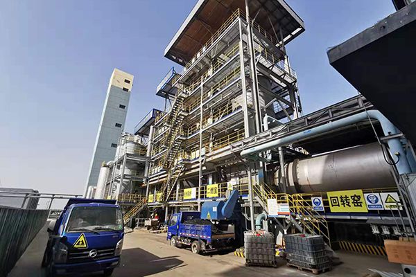
- Hazardous Waste Treatment System After introducting rotary kiln technology and software from Japan in 2014, Zhongding has established 45 rotary kiln-based hazardous and medical waste treatment centers. Learn More
Our Waste Handling Equipment
-
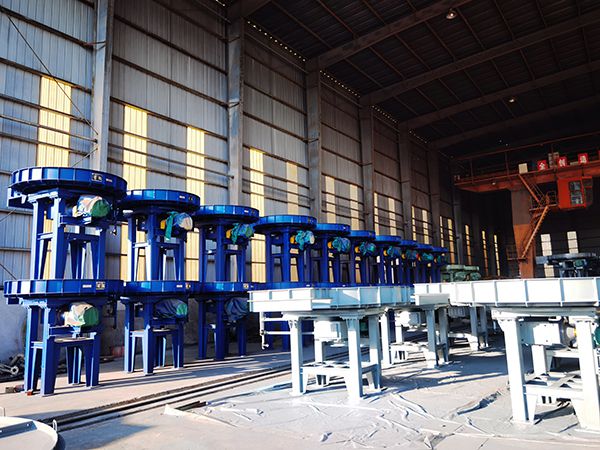
- Disk Feeder As a professional disk feeding system manufacturer, Zhongding is experience in researching, developing and producing for over 30 years.
-
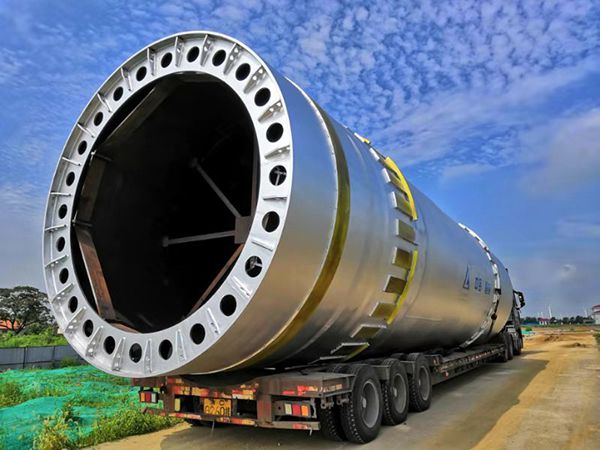
- Rotary Kiln Zhongding is a leading non-standard environmental protection equipment manufacturer in China. Our direct-fired rotary kiln is known for its durability, efficiency, and quality.
-
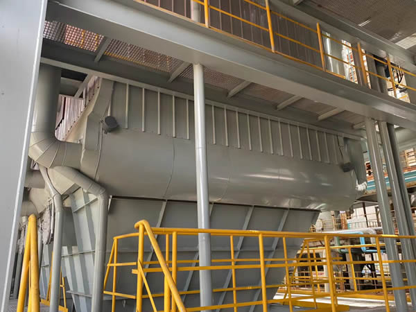
- Baghouse Dust CollectorZhongding specializes in the development, design, and production of dust removal and dust collection equipment, which are widely applied in various industries such as metallurgy, cement, steel, chemical, power sector, etc.
-
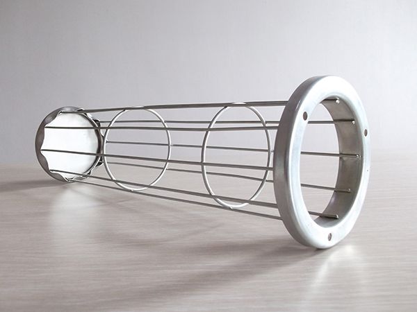
- Filter Bag Cage Filter bag cage, also known as dust collector cage or baghouse filter cage, is formed by one-time welding with specialized equipment.


